Table Of Content
Everybody has to start somewhere, especially in 3D printing, and LittleArm is the ideal entry level project to get you hooked on 3D printed robotics. With only 3 degrees of freedom, meaning 3 points of movement on the arm, it is very easy to understand, both when 3D printing and programming. The collaborative robot is a robotic arm purpose-built for hybrid work. Certain safety features allow for significant risk reduction in hybrid work environments. This is a relatively new robot type and its uses are still being explored.

Industrial and Warehouse Robotics
For welding, material handling, pick-and-place tasks, and dispensing, articulated arms are perfect. There is essentially no place in their work envelope that they cannot reach because of their multiple axes and degrees of freedom. As a result, articulated robots are among the most adaptable, flexible, and space-saving designs available. It's crucial to keep in mind that articulated robots are by nature dangerous. It may be more dangerous for operators to install an articulated robot in a situation where there is no risk mitigation.
Notable applications of Robotic Arm
Finally, for the companion computer, I’m using a regular laptop with MATLAB R2015a installed on it. Any personal computer can be used, provided that it has the minimum recommended specifications to run MATLAB software. Our mission is to inspire humanity to adapt and thrive by harnessing emerging technology. It sends status updates or alerts to the external source, signaling that the operation is finished or requiring intervention if issues arise. In the 18th century, Von Kemplen's left arm was a clever chess-playing robot. Now, take the power cord and thread it through the two holes on the frame.
Robotic Arm: Components, Types, Working & Applications
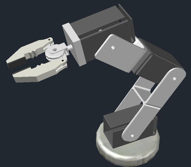
The claw can grab anything from a piece of cupboard or marker up to a table tennis ball. For the claw’s inclination motor to work properly, the total mass of the claw and load shouldn’t exceed 600g. To make the connection between all electronic components, they are wired together on a breadboard, situated behind the robotic arm. It’s more complicated to connect the motor’s wires to the breadboard because they have to cross all the moving parts of the robot. It’s important for the mobility to be ensured and for the arm to be able to operate at all angles. In other words, the arm must rotate at the maximum angle without being bothered by the wires.
Cobots adopt strong-arm tactics - DEVELOP3D - Develop3D
Cobots adopt strong-arm tactics - DEVELOP3D.
Posted: Thu, 25 Apr 2024 07:53:14 GMT [source]
More about MIT News at Massachusetts Institute of Technology
This second third-class lever has the fulcrum in joint B and the force applied in Joint C. The whole point of using levers is to take advantage of the arms’ rapport. In the case of the boom, distance E-F represents nearly three fifths of E-G. Doing so we are able to fit smaller motors with less electricity consumption and still get the same output of force. The power supply must be able to provide the required current for all motors. I have connected my bench power supply adjusted to 6 VDC, which can provide up to 5 A. The Arduino UNO board is powered from the USB cable connected to the companion computer, which also powers the bi-phase encoder.
The angular position of the DC motor is controlled with a PID control loop. The remaining servo motors are controlled with open-loop control signals, because servo motors already have closed-loop controls implemented in hardware. Applications that require a machine to twist and manipulate the product at odd angles can be a good match for robotic arms. Specifically, the articulated arms are like six-axis and collaborative. This task often requires the robot to move at angles in several different planes.
During the execution of commands, all angles formed by motor, forearm, arm and rod are slightly modified. To avoid stress in the components, all of them must be fixed in pivoting joints. It requires fine measurements for alignment, not to mention enough space for the rod to extend. There are free online apps to calculate torque for robotic arm joints [4]. You need to provide inputs, such as the configuration of the robotic arm (how many degrees of freedom it has), link lengths, link weights, loads and so on. The DC motor at joint 1 is a generic JGY370 DC motor [1] that spins at 6 RPM when powered with 6 VDC.
Adding actuators and motors to your robot arm is not a difficult task, but there are a few things you need to keep in mind. First, you need to make sure that the actuators and motors you choose are compatible with your robot’s frame. Second, you need to make sure that the actuators and motors are properly secured to the frame. And third, you need to make sure that the actuators and motors are properly wired.
This means they don’t have the same flexibility afforded to articulated arms. This limits them in some respects but gives them certain advantages over articulated arm types. Robotic arms are one of the most identifiable pieces of robotic machinery in industrial settings.
UWF students earn award from NASA at Human Exploration Rover Challenge - UWF Newsroom
UWF students earn award from NASA at Human Exploration Rover Challenge.
Posted: Fri, 26 Apr 2024 15:31:38 GMT [source]
They offer high speed and precision in a horizontal plane while maintaining rigidity in the vertical direction. Cartesian robotic arms, or gantry robots, utilize a cartesian coordinate system (X, Y, Z) for movement. They feature linear motion along each axis, providing precise and predictable movement in a structured environment. To provide a better understanding, we have explored the various components, types, and applications of robotic arms in this article. In the beginning of this century, robots were considered to be the future of manufacturing. Let us understand what robots are and how they are used in an industrial setup.
However, its usage and importance have grown significantly in the last 10 years, mainly because every industry and individual seek automation. See, it is very important to understand that robots are not only meant to fascinate the general public, perform stunts in the street or walk and talk. In fact, robots can be programmed to perform ANY task that even a human cannot do (e.g. high precision cutting). You can also use plastics like acrylic, which will provide you with all the strength you need to hold everything together as you slowly add heavy components.
The links are connected by joints, which provide the necessary rotational and translational capabilities to the mechanism. The part of a robotic arm design which interacts with the environment is usually the last link and it is called the end effector, or end of arm tooling (EOAT). I have chosen a DC motor for the first joint at the base of the robotic arm specifically to illustrate angular position embedded PID control. By including it as a hardware and software implementation example, it serves as a means of studying the concept; hopefully easy to understand for those new to this concept.
This means that these callback functions must contain all the code you want to run in response to interactions with these controls. Robotic arms are extensively used in manufacturing for assembly, welding, painting, and material handling tasks. Once the robotic arm has completed its assigned tasks, it may return to a designated resting position or await further instructions. Throughout the movement execution process, the control system continuously receives sensor feedback to ensure that the robotic arm moves accurately and safely. Based on the input commands and sensor data, the control system generates a motion plan that specifies the desired trajectory for the robotic arm to follow. This data provides crucial information for the robotic arm to perceive objects, measure distances, assess forces, and ensure safe and accurate operation.
Revolute joints enable rotational movement, prismatic joints allow for linear motion, and cylindrical joints combine both rotational and linear movements. Getting back to the engineering of robotic arms, most of them have stepper motors implemented directly in the joint—or, for simplified models, in the fulcrum. Those stepper-motor models have an extremely short arm, only the radius of the axle. This causes a considerable disadvantage because the loading force will always have the point of application at the top of the boom and the only solution is to equip it with powerful motors. In this project, our model is inspired by heavy-duty machineries, such as excavators. Such equipment is capable of digging out 1.5 tons on average, being powered by high-pressure hydraulics.
Some applications require a human-robot mix to operate at peak efficiency. Collaborative robots are positioned to handle these types of applications. Material handling applications often deploy collaborative robot technology. This means a human operator can load raw materials into a staging area near the cobot while the robot handles the loading and unloading of the material into a machine. Cylindrical robot arms are designed around a single arm that moves up and down a vertical member. These robots are very compact and are deployed for small and simple tasks.


No comments:
Post a Comment